Danfoss Return Temperature Limiter FJVR Valve bodies
- Stock Code
- Related Material
Stock Code Description
| D003L1000 | FHV-FJVR |
| D003L1040 | FJVR sensor 10-50C |
Please click HERE to see all Brochures, Spec-Sheets & Installation Guides
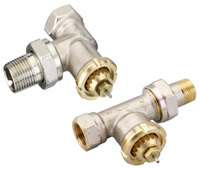
The FJVR valve (normal flow) is used exclusively in conjunction with the FJVR return temperature limiter sensor. The FJVR valve is mounted in the outlet of a radiator or floor heating circuit. The valve and sensor can be fitted in any position as long as the flow direction is observed.
Stock Code Description
| D003L1000 | FHV-FJVR |
| D003L1040 | FJVR sensor 10-50C |
Please click HERE to see all Brochures, Spec-Sheets & Installation Guides

The Danfoss floor heating manifolds are used for heat regulation in floor heating systems. Both flow and return manifold have 1” connections, with connections for between 2 to 12 heating circuits. The manifold is equipped with Danfoss’ integrated valves with pre-setting for easy installation and commissioning. The valves are controlled by Danfoss’ TWA thermal actuators. A full programme of manifold accessories, including brackets, end sections with drain taps and automatic air vents, ball valves, thermometer and reduction pieces, is available.
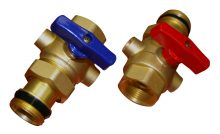
Continuous brass manifolds used for controlling water flow in Hydronic floor heating systems. The supply side manifold comes with or without flowmeters. The return side manifold is equipped with integrated Danfoss pre- setting valves for easy balancing.
A range of high quality accessories for FHF Manifolds including:
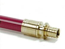
In hydronic floor heating systems water is heated in a boiler and circulated at safe low pressure at around 35 – 40C through extremely durable plastic pipes laid in or under the floor.
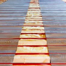
The Diffusion Plate System accommodates 16mm heating pipes and uses 0.8mm thick aluminium plates to diffuse the heat over the floor area. The heat is then transferred through the floor surface into the room. Due to the high conductivity of the plates the reaction time compared to traditional screed systems is reduced.
This system has been designed for timber joist floors or battened timber floors over concrete slab applications with hydronic floor heating systems. Insulation is required under a suspended timber floor application and is recommended when installed over a concrete floor.
Size: 1.0m x 0.338m in 0.8 thick Aluminium with 200mm 2-channel pipe spacing. Conductivity 160W/mK.
Maximum thickness of wood surface over the diffusion plate: 20 mm.
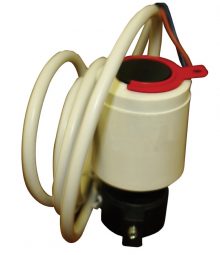
The thermal actuator TWA range is used with electrical on/off-controls to activate several types of valves and floor heating manifolds. The actuator is equipped with a visual position indicator to show the open or closed position of the valve. The TWA-actuator can be connected to the RA, RAVL and RAV valves from Danfoss. Furthermore versions for valves with M30x1.5 connection are available. The actuator is made for either 24 V (SELV) or 230 V supply in both normally closed (NC) or normally open (NO) versions (valve positions with no supply voltage to the actuator). The 24 V actuator for RA valves also comes in a NC/S-version having an end-switch.
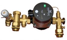
The pre-fabricated floor heating mixing shunts are used for regulating the correct flow and supply temperature into the hydronic floor heating system. Compact mixing shunts for regulating flow and supply temperatures in floor heating systems. Their compact and flexible design allows the shunt to be mounted on either side of the manifold. A self-acting proportional regulator is used to regulate the supply temperature to ensure it is always constant and at the required temperature.